Workflow Engine Workshop

Introduction
Welcome to your workshop on the Workflow Engine! The purpose of this workshop is to give you real, step-by-step instructions on how to accomplish and use most of the tools we covered throughout the course.
This workshop builds on the Course Four Workshop and will guide you through creating workflows and illustrate how to use advanced workflow features.
Let’s begin.
The Story
First, let’s recall the story of the application we are building:
Embree is launching an initiative to adopt IoT and offer new capabilities to their customers. Currently, Embree produces water pumps for industrial use cases like mining, construction, and oil & gas. Their goal is to gain deeper insight into the pumps and provide more value to their customers.
To begin the new initiative, the Embree team decided to start with a proof of concept, which will enable them to solve a small, useful problem to get results faster. For this first project, Embree wants to take one of their existing pumps and send the data it’s collecting, like flow rate and temperature, to the cloud.
To build this proof of concept, they chose to use Losant. They chose Losant because the user experience would allow them build this proof of concept in no time and they could easily build new applications with the insights gained.
In Course Three, we created a device that represents our water pump with the following attributes:
- Battery Voltage
- Valve Status
- Flow (liters per second)
- Temperature
- RPM
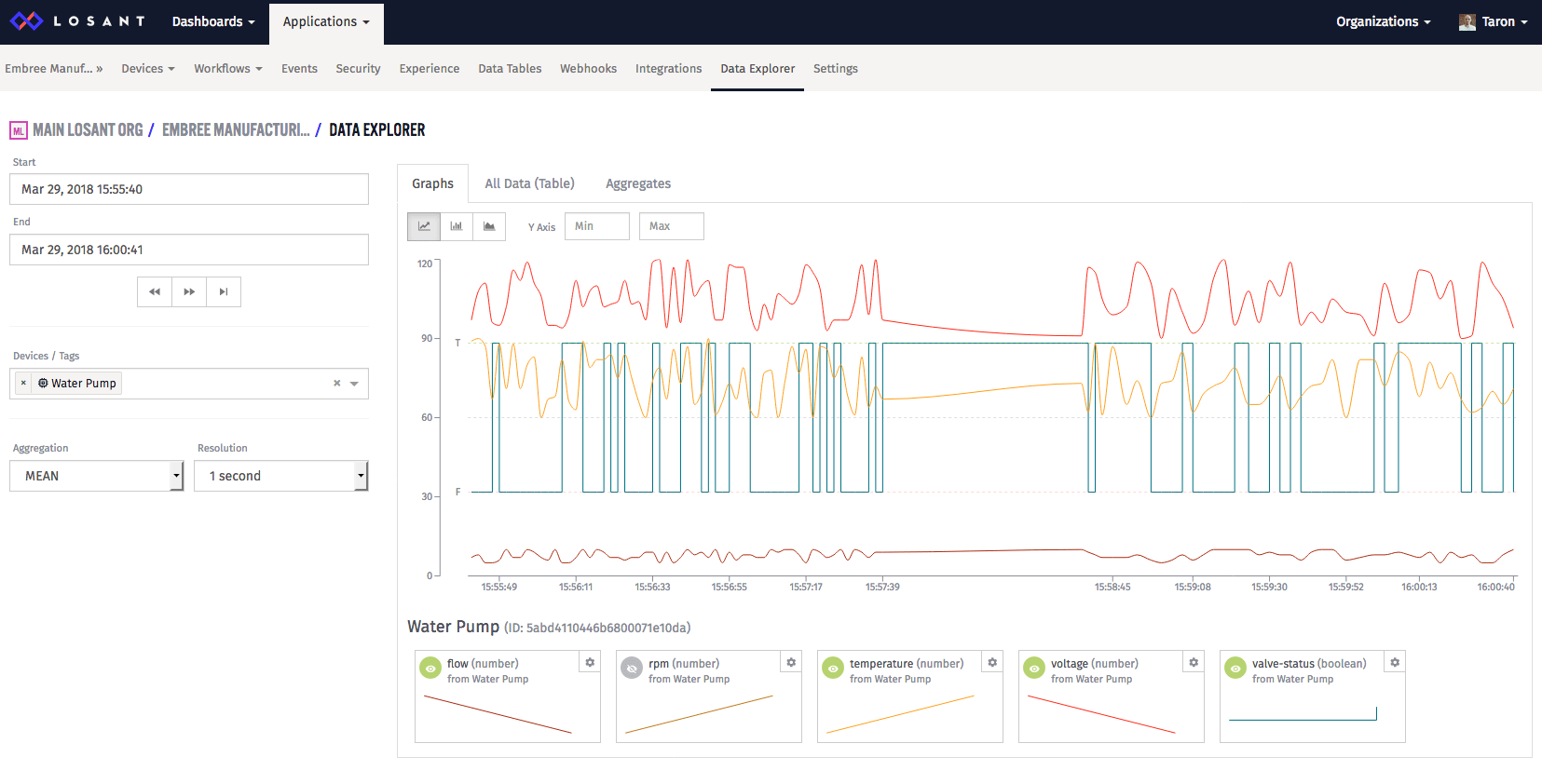
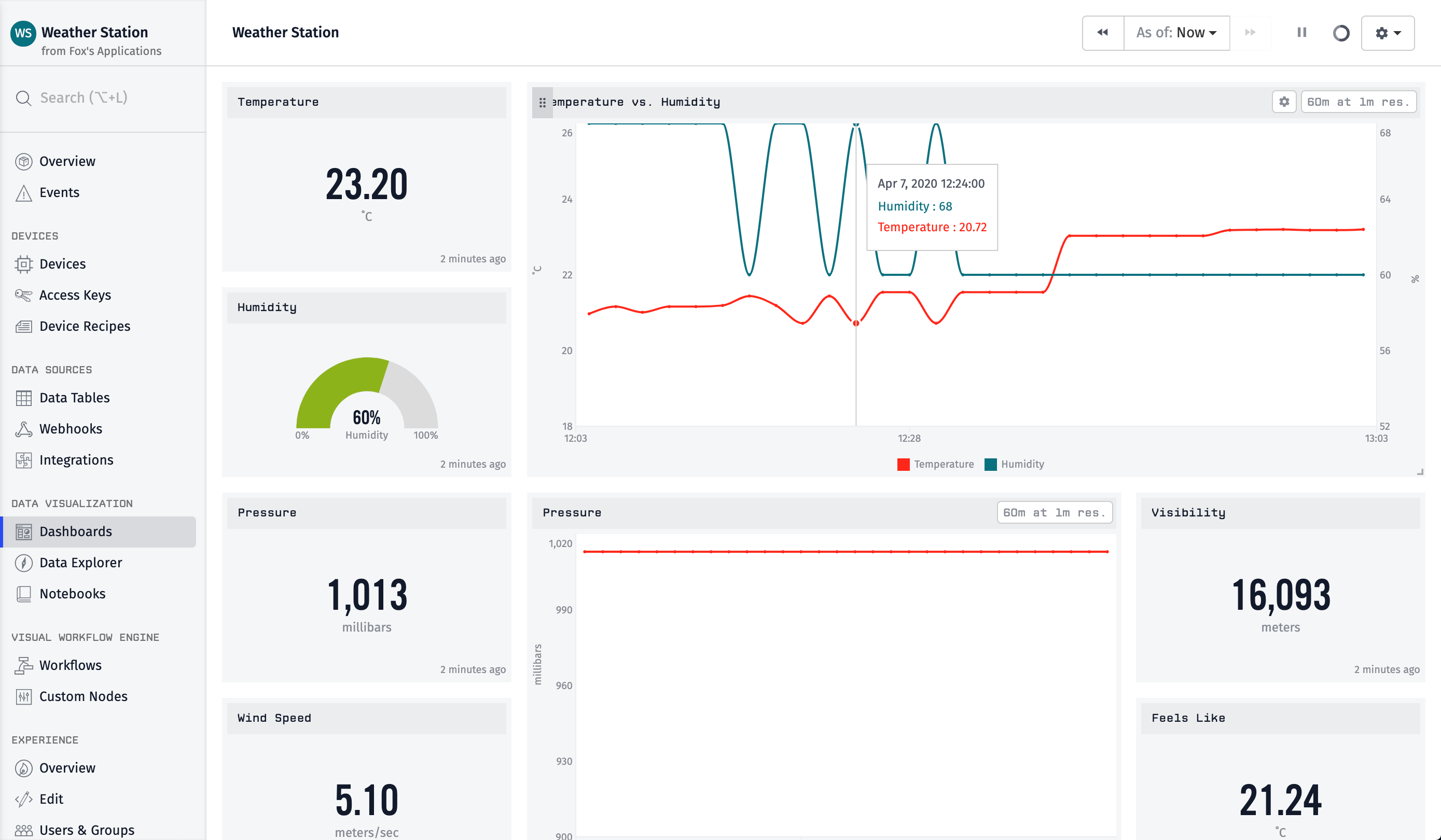
Then, we simulated the data and did a simple analysis using the Data Explorer:
In Course Four, we took a look at different visualizations, reporting, sharing, and all the dashboarding features in Losant. In the workshop, we created a dashboard that supports Context Variables, which allows us to add hundreds and thousands of pumps and each had have their own dashboard.
Now that we’ve covered Workflows, we can take our application to the next level! In this workshop we are going to:
- Use the Workflow Engine to simulate device data permanently.
- Configure an Input Control Block to trigger a workflow.
- Use the Workflow Engine to email an alert when a devices’ state is out of range.
Let’s begin.
Part One: Simulate Devices
The Device Simulator is excellent, but its one limitation is that you need to keep the browser window open to simulate devices. Lucky for us, we can use the Workflow Engine to always simulate data without the simulator. This ensures, from here on out, you’ll always have device data within your application.
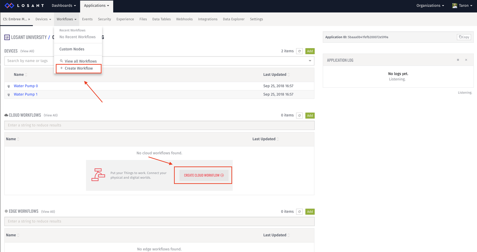
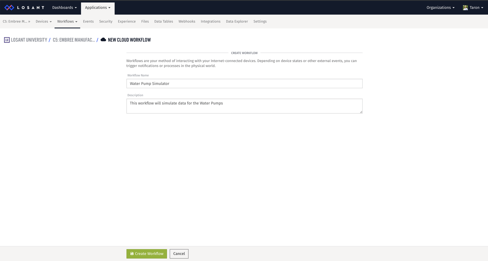
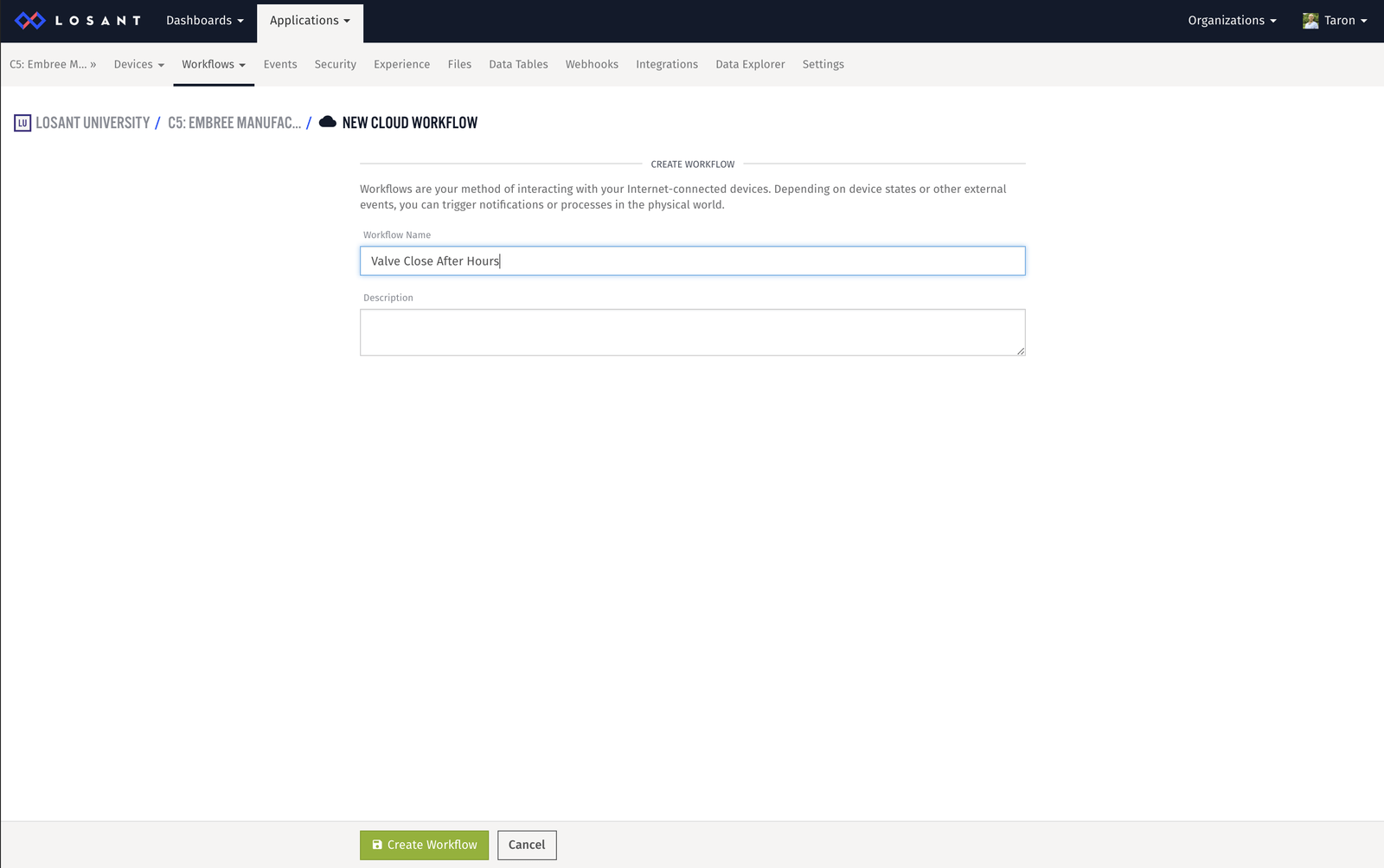
First, let’s create a workflow. You can create a workflow by going to “Create Workflow” in the Workflows dropdown menu.
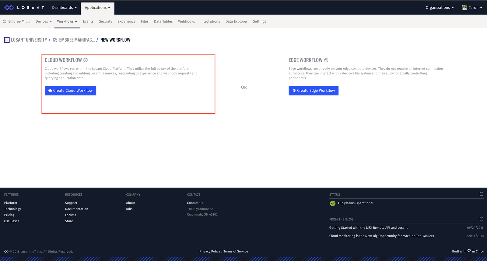
Be sure to create an Application Workflow:
Next, you can give the new workflow a name and description:
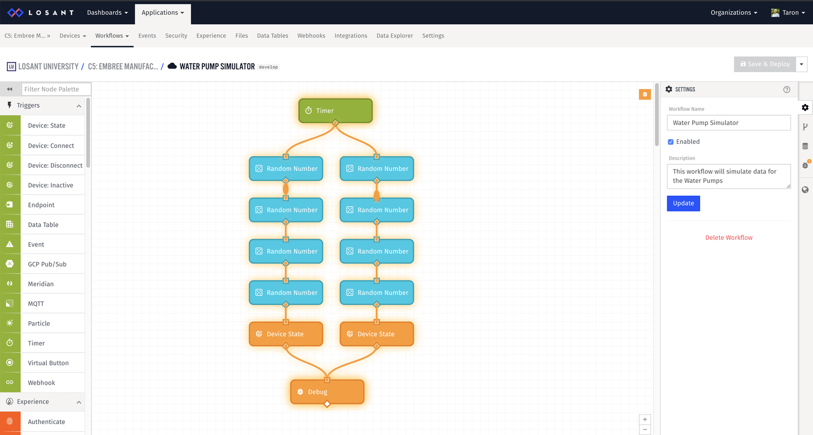
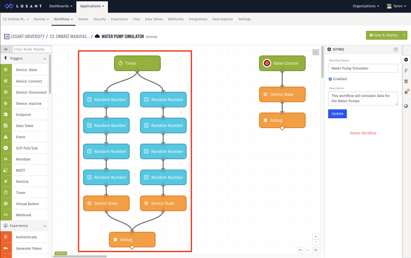
Now, that you are at the in the Workflow Canvas, it’s time to start building! Here is the workflow we are going to build to simulate data:
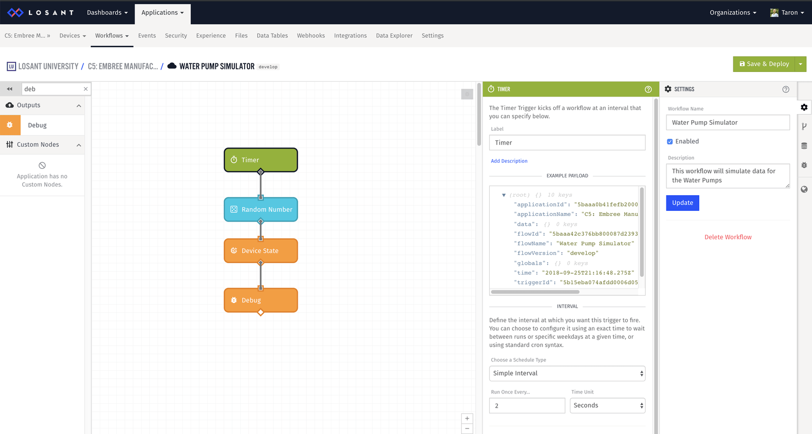
The goal of this workflow is to, on an interval, generate a random number that represents temperature, and report the temperature state to Water Pump 0. To do this we need the following nodes:
- Timer Trigger - to trigger based on an interval
- Random Number Node - to generate a random number
- Device State Node - to report state
- Debug Node - to inspect the payload
Let’s walk through each node configuration.
Timer Node
Our simulator ran every two seconds. So, we can configure the Timer Node to do the same:
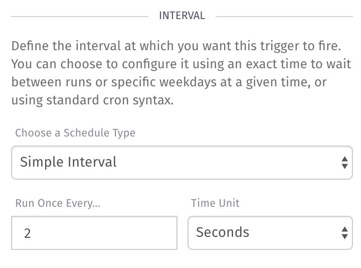
Timer Node Configuration:
- Schedule Type: Simple Interval
- Run Once Every: 2
- Time Unit: Seconds
Random Node
The Random Number Node generates a random whole number within a range of your choosing and stores the number in the payload for use by subsequent nodes.
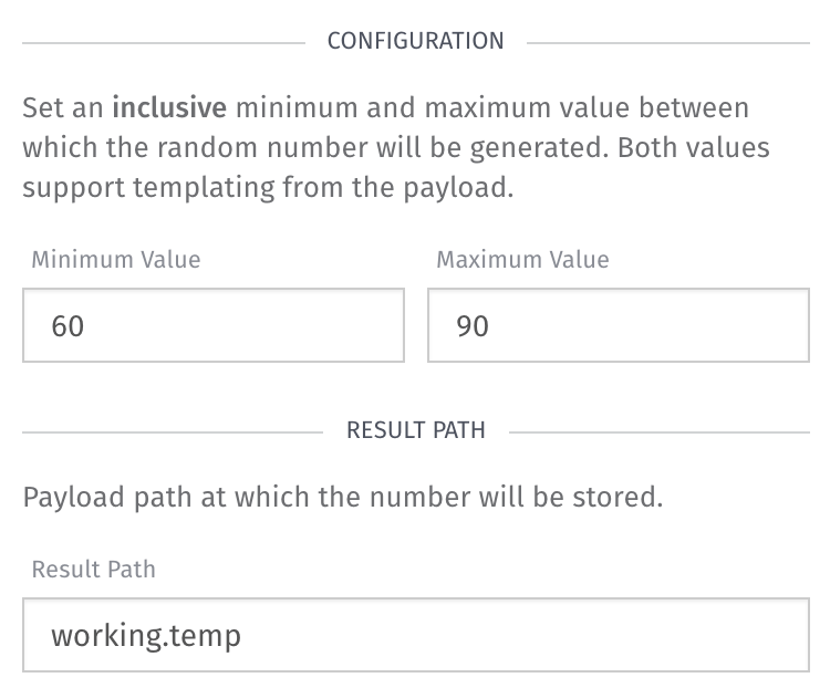
Random Node Configuration:
- Minimum Value:
60 - Maximum Value:
90 - Result path:
working.temp
If you would like to simulate different values, feel free to update these to your liking.
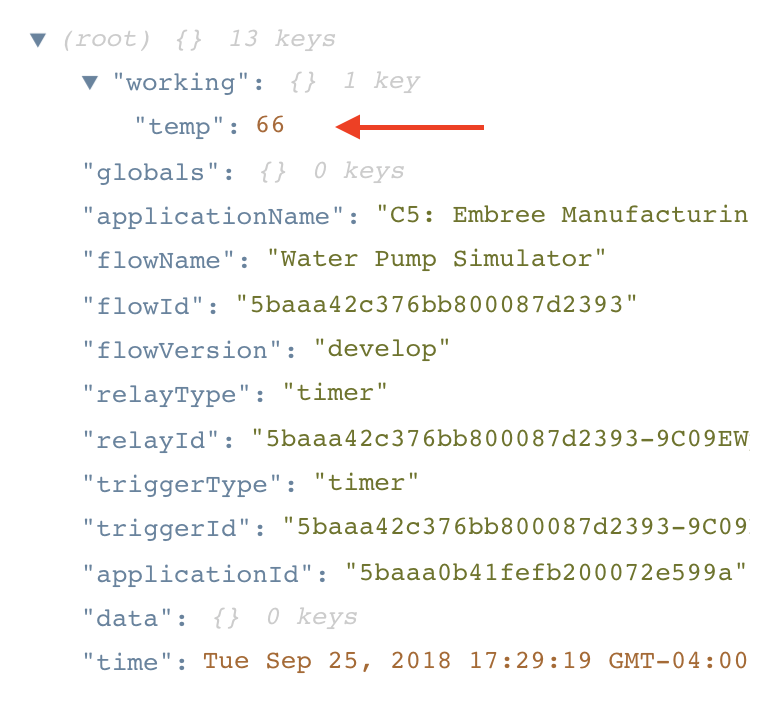
One key thing to notice here is the “Result Path”. This is where the Random Node will place the random value it generates, so that you can use it later.
Device State Node
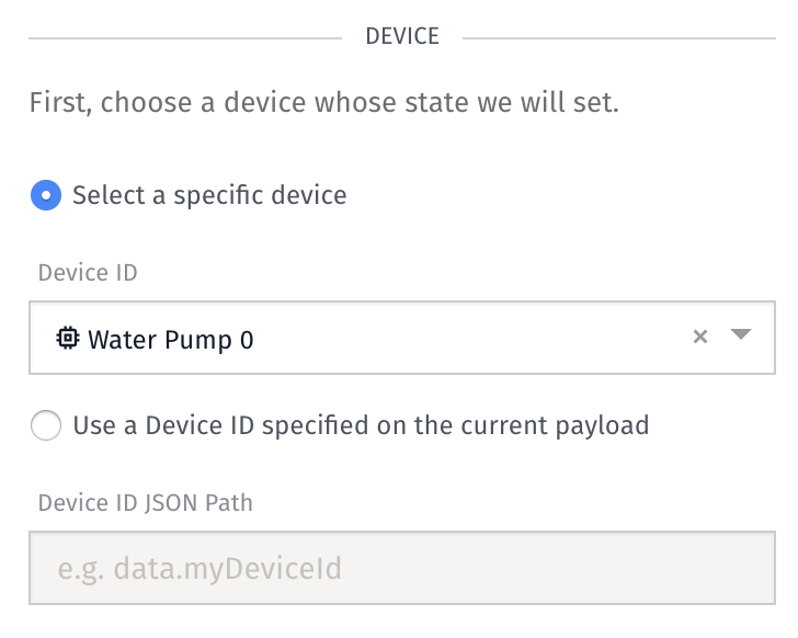
Lastly, we need to configure the Device State Node to tell it which attribute we would like to report our random data to.
First, we need to select a device:
Next, we need to update the temp attribute value:
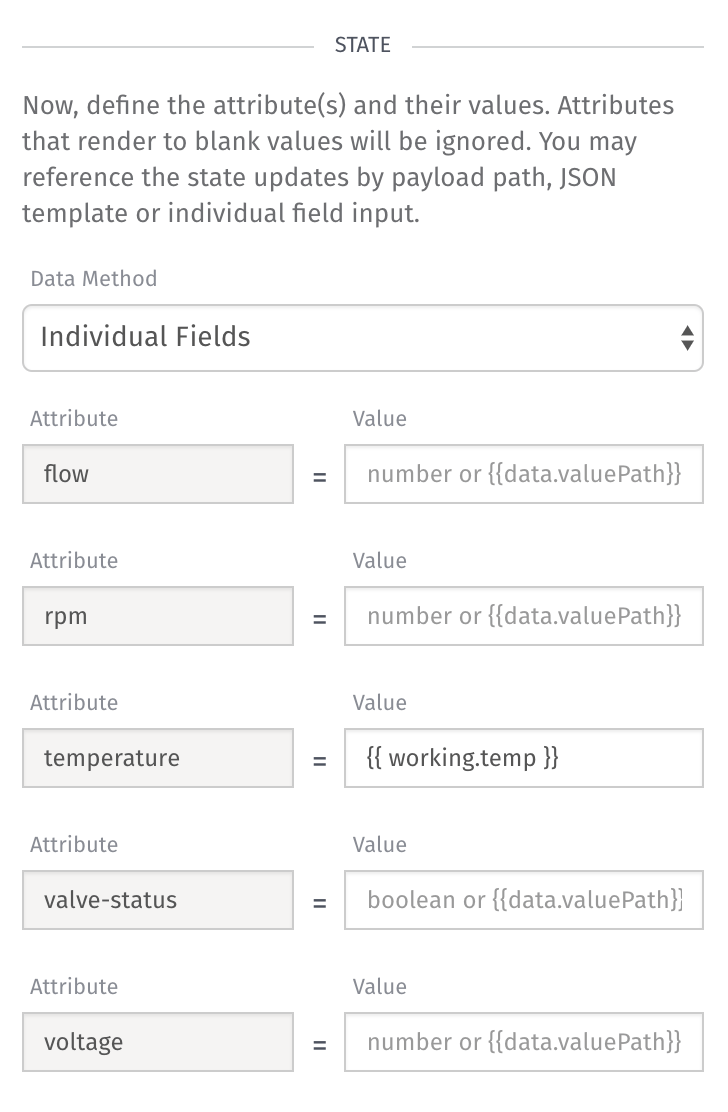
These value fields are templatable. We know this because the curly bracket is used in the input example. Under the temperature attribute, we need to set the value to:
So, when this workflow runs, it will report our randomly generated number as state for our device.
Save and Deploy
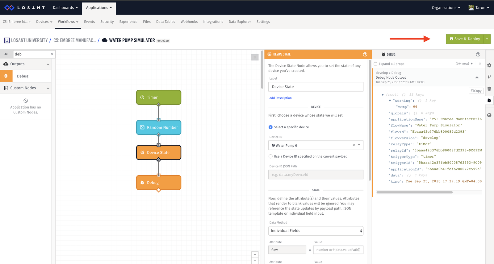
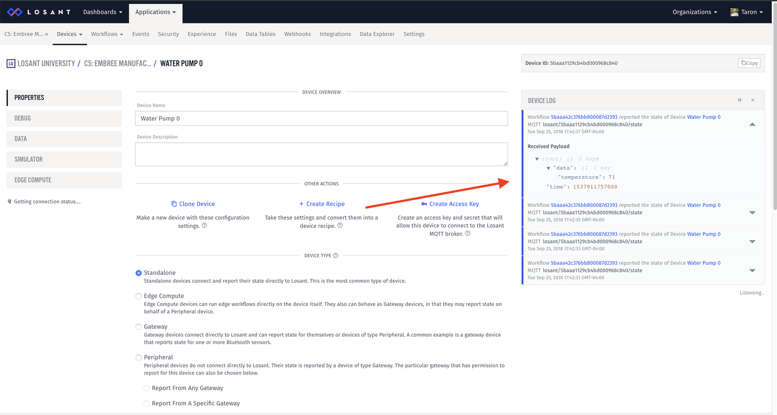
Now that our workflow is running, we will immediately be able to see the debug message appear every two seconds, and if you take a look at working.temp you’ll find the random data.
Also, if you take a look at your device properties page, you can see the state messages appear in the Device Log:
Exercise
For this exercise, you have two tasks:
- In your workflow, simulate data for the following attributes:
- flow
- rpm
- voltage
- Since we have two water pumps, simulate data for the second as well.
Feel free to come up with your own values that makes sense. However, for reference, here is what we were doing with the simulator:
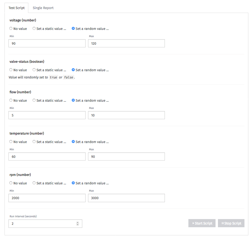
If you need some guidance, here is what my completed workflow looks like:
Now, notice we did not simulate the value status. Let’s do that.
Part Two: Simulate Value Status
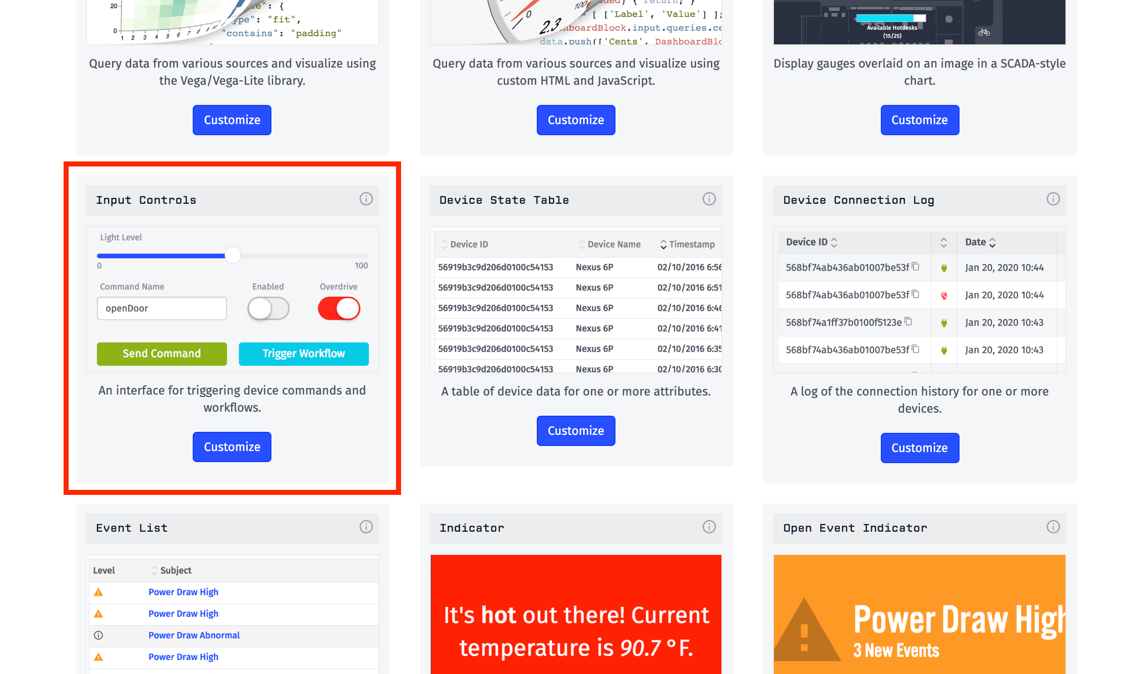
In the Input Control Block Chapter in Course Four, we talked about how you can trigger actions from a dashboard, such as triggering workflows. When triggering a workflow from an Input Control Block, behind the scenes you are triggering a Virtual Button. For our use case, we can use the Input Control Block to open and close the water pump valve.
Let’s build this.
Workflow
Before we can build an Input Control Block to trigger a Virtual Button, we need to create the Virtual Button to trigger.
In our Water Pump Simulator workflow, let’s add a new workflow path:
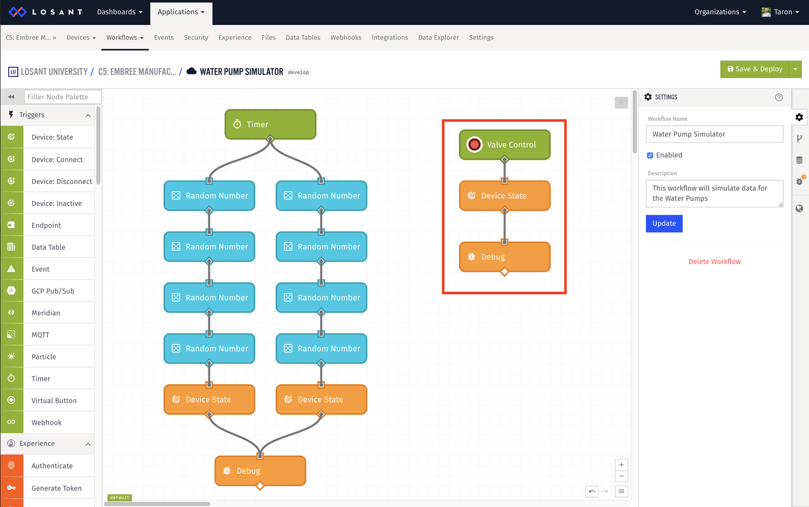
This new path consists of:
- Virtual Button Trigger - to trigger using a button
- Device State Node - to report valve state
- Debug Node - to inspect the payload
We don’t need to do any configuration for the Virtual Button or Debug Node. Let’s configure the Device State Node:
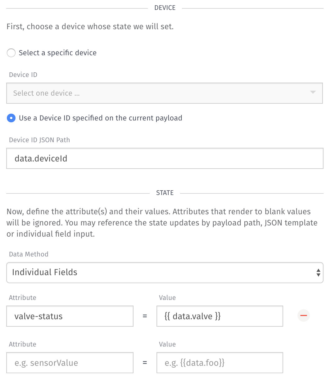
For the device, we want to specify a “Device ID JSON Path” of:
data.deviceID
Later on, we are going to configure the Input Control Block to pass this data to the Virtual Button so we can make use of it here.
We also want to configure the valve-status attribute:
- Attribute:
valve-status - Value:
{{ data.valve}}
Just as data.deviceID, data.valve will come from the Input Control Block.
Input Control Block
In order for everything to work properly, our Input Control Block needs to trigger the Virtual Button we just created. However, when it triggers the Virtual Button, we need it to send along the deviceId of the device to control, and the valve-status to change to. We’ve set up our button to accept this, now we need the Input Control Block to send this data. Let’s configure it.
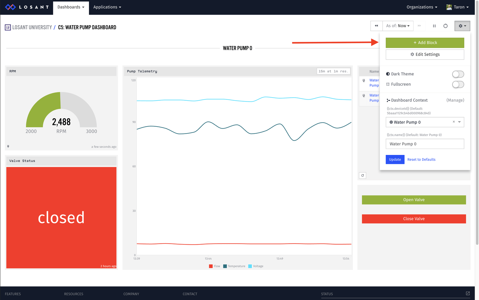
Add an Input Control Block to the dashboard:
Next, configure the name, description, and application.
Then, add two button controls. One to represent “Open Valve” and the other “Close Valve”.
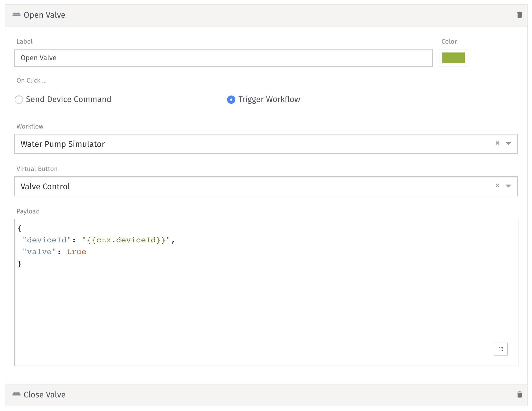
Here is the block configuration:
- Label:
Open Valve - Color: Green
- On Click: Trigger Workflow
- Workflow: Select your workflow that contains the Virtual Button we created earlier.
- Virtual Button: Select the appropriate Virtual Button in the respective workflow.
- Payload:
{
  "deviceId": "{{ctx.deviceId}}",
  "valve": true
}
With this configuration, we are tying the input control button to the Virtual Button on the workflow. When triggering the Virtual Button, the Input Control Block will use the contents of the “Payload” configuration as the data of the Virtual Button. In this case, it will send a deviceId and valve. These values correspond to the data we expect in the Device State Output Node in our workflow.
Another thing: Our dashboard supports Context Variables. Since we have access to these variables within the block settings, we can use {{ctx.deviceId}} as the Device ID. So, no matter the device, my Input Control Block is flexible enough to know what device I want to control.
Exercise Two
Since we didn’t walk through this one, configure the “Close Value” input control button.
Once done, and because we also have a Live Stream Indicator Block (bottom left), we can see the value status update in real time:
Part Three: Alerting
When Embree started down this path, the goal was to take one of their existing pumps and send the data it’s collecting, like flow rate and temperature, to the cloud. The natural progression of this problem is to be alerted when any of the pump telemetry data goes out of a range.
Because we are solving a different problem, let’s create a new workflow:
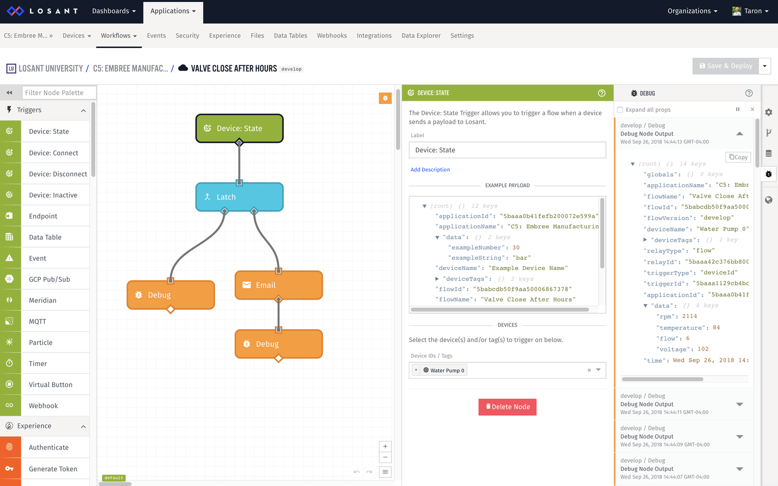
This new workflow consists of:
- Device: State Trigger - to trigger the workflow when our device sends data
- Latch Node - to do one-time branching to check our alert
- Email Node - to send an email
- Debug Node - to inspect the payload
Let’s configure them:
Device State Trigger
The Device: State Trigger allows us to trigger this workflow when our water pump reports state. Because we have another workflow simulating data every two seconds, we can listen for state.
In the configuration, all we need to do is select our device(s);

For simplicity, I just chose one water pump.
Latch Node
Recall that the Latch Node allows us to do one-time branching. Instead of evaluating an expression every time—like the Conditional Node—if our expression results to true, the latch node will "latch" to false. So, once it detects our threshold warning and sends the email, the node will latch to false and we won't continue to get emails. If we were to use the Conditional Node here, we would get an email every time our device reports — this is currently every two seconds.
Let’s configure this node:
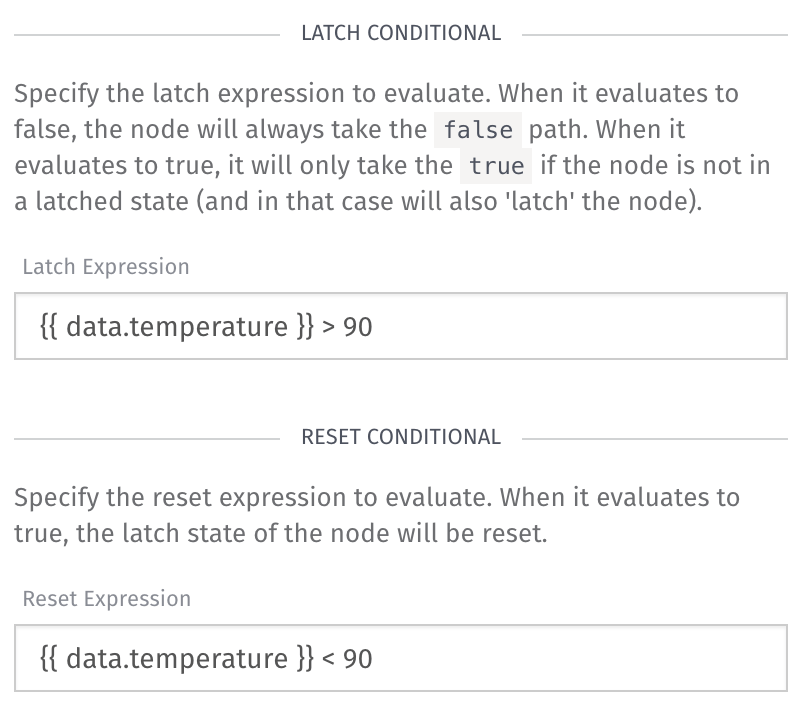
Here is the configuration:
Latch Expression:
Reset Expression:
Here, we are checking if our temperature is above 90 degrees. If this were to happen, the Latch Node will only take the true path (right) once — until the reset conditional is true, thereby resetting the 'latch'. We only want to reset the latch when our device is back to “normal” or under 90 degrees.
Email Node
Now we just have to configure the email:
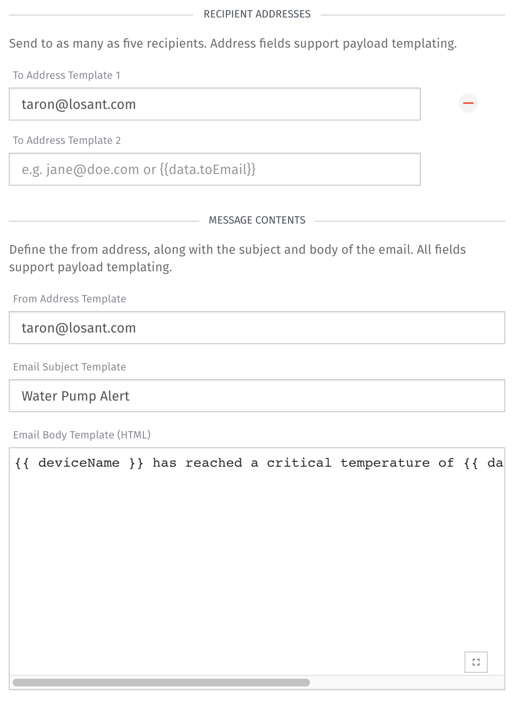
Here is the configuration:
- To Address - Your email
- From Address - Your email
- Email Subject -
Water Pump Alert - Email Body -
Testing
If you would like to test this workflow out in different scenarios, you can simply force a state update in Losant:
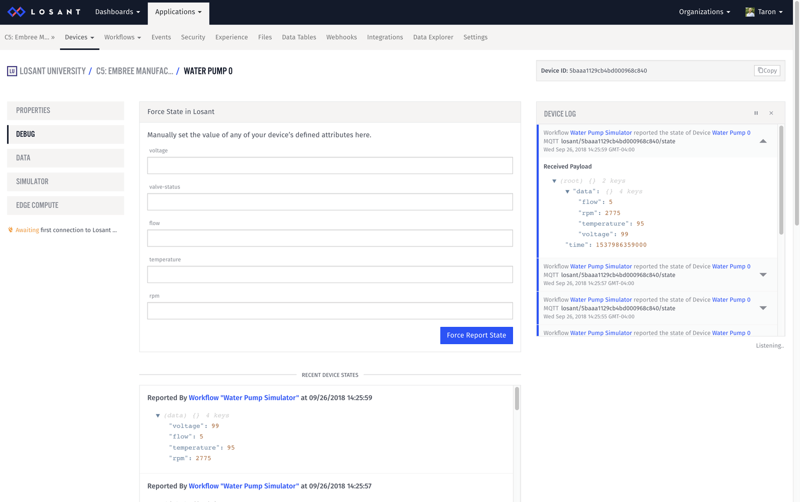
If you report a state of above 90 degrees, you’ll get an email that looks like this:

All done
Now, we are beginning to have a more complete application on our hands.
- Use the Workflow Engine to simulate device data permanently
- Configure an Input Control Block to trigger a workflow.
- Use the Workflow Engine to email an alert when a devices’ state is out of range.
More to Explore
If you already have problems that you would like to try out, please do! There is a ton more you can do with your application. Here are a few examples:
Custom Nodes
If we added a new water pump, we would have to copy/paste and adjust all the Random Number nodes; this could get messy. However, since you know your device and how you would like to randomly generate data, you could easily build a “Water Pump Simulator” random node that can do this workflow you.
Connect to External API
In this workshop, we didn’t bring in any external data. Try bringing weather data into our application, and build a dashboard around it. There is already complete instructions on how to do this in the Losant Walkthrough.
What's Next?
Congratulations, you are now officially done with Course Five of Losant University!
Feel free to poke around Losant; there is a ton to explore. If you run into any troubles along the way, the Documentation and Forums are there to help.
Was this page helpful?
Still looking for help? You can also search the Losant Forums or submit your question there.